THE WORLD'S LARGEST NORCAL SIERRA - FROM THE ARRL HANDBOOK
May 2008
In the end, the many questions along the way, construction obstacles, and correct circuit operation issues were eventually all overcome for the pleasure, challenge, and learning experiences alone. Would I do it again instead of ordering the kit? Not sure. There is a point in a lengthy construction project when a guy 'just wants to get on the air'. Support for this was limited (Although I did receive a very helpful email from Wayne N6KR, after all these years about the sidetone!), yet the regular and even some unregular construction pitfalls remained with all my parts substitutions.
Am I a better ham than before for having tried this project? I think yes.
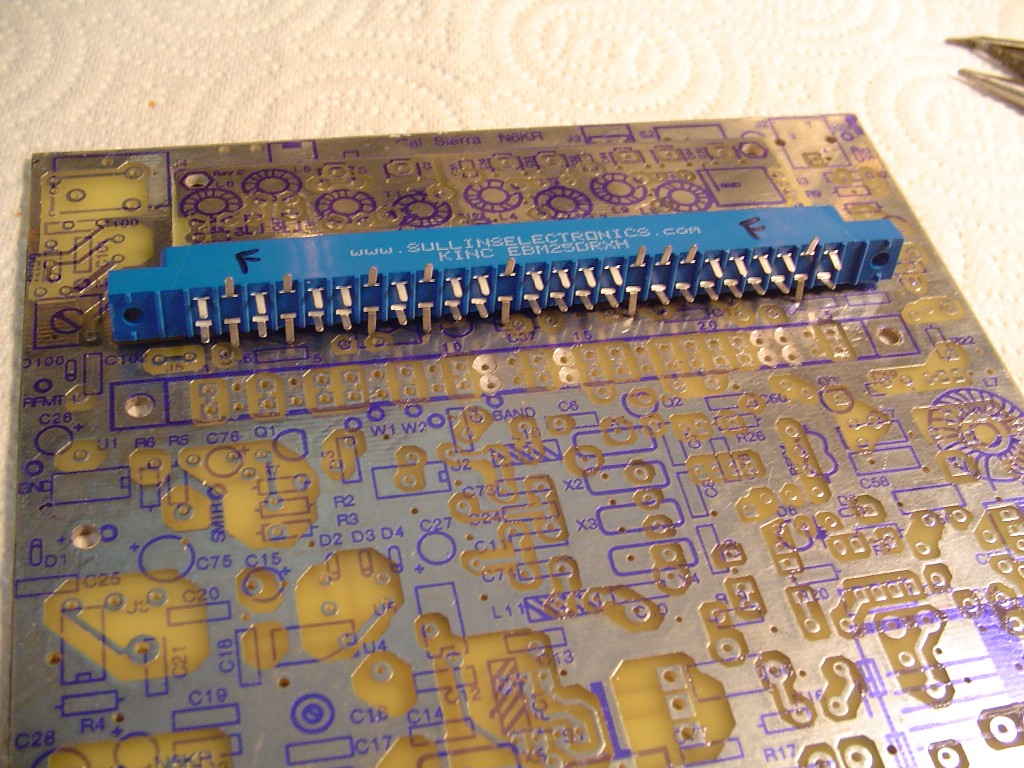
Finding the Sullins connector for it took a bit of research all by itself. The FAR board did not want to fit it all that well as far as the hole pitch (Spacing) anyway. Also it was important to bend some of the pins on the connector out before final assembly as there would be no way to solder them onto the top traces later otherwise.
I was disappointed the component silk overlay was printed on the wrong side of my FAR board. That made things interesting right away.
The band connector was the first component I installed, and I put it on the wrong side due to the overlay was perfectly printed to align with the connector pins and attachment screw holes (On the wrong side of the board). It was no fun de-soldering the 50 pin connector!

Another example of this would be R100 on the band module boards that is not discussed or shown in the ARRL article or prints. I discovered later R100’s had to do with band identification information for the KC-2 keyer/counter that came later at Wilderness Radio. I constructed the metering circuitry from the article print on a separate ‘Manhattan’ style board and worked fine.
I decided to build the band modules for 40, 30, 20, and 17m. 40m first of course to see if I could just get things working.
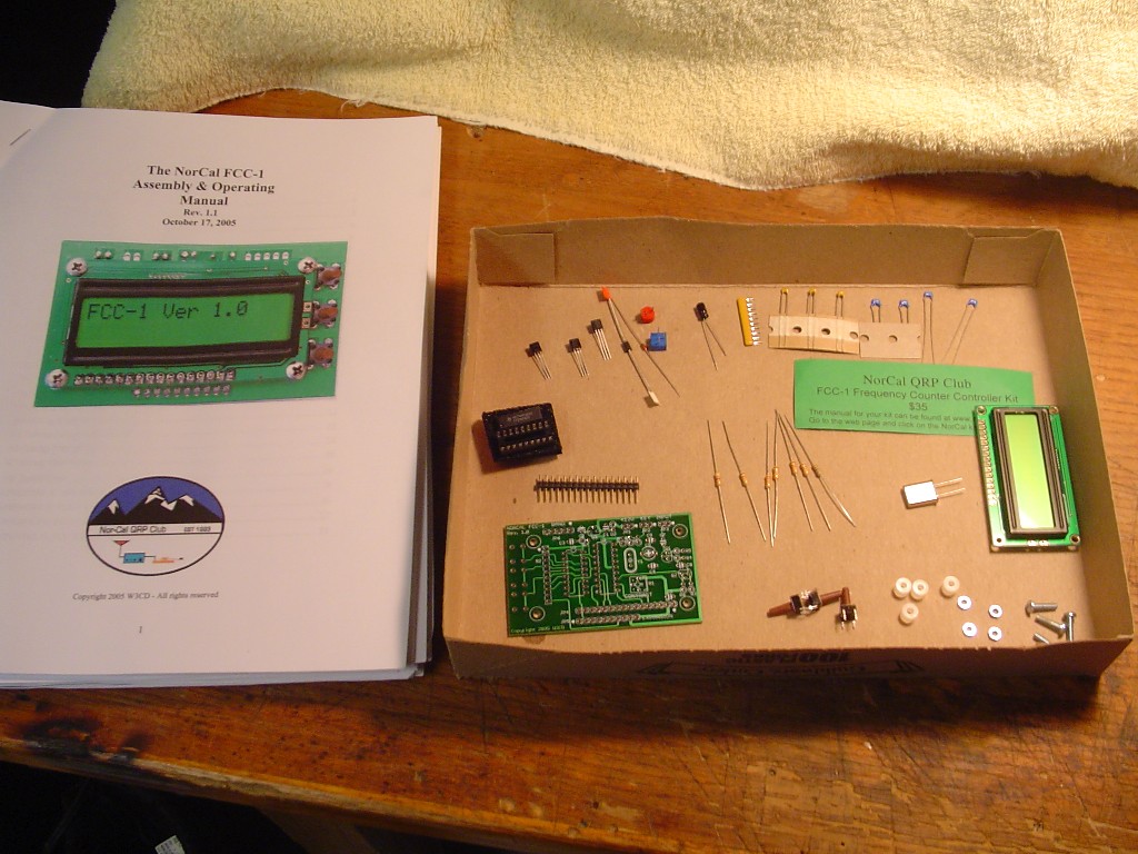
I also constructed another Norcal keyer for this rig and had
a problem with it powering up key down. This was the fourth Norcal keyer for me
and I never had problems before. After a couple of emails were exchanged ON A
HOLIDAY WEEKEND with the Norcal guys I was told they have changed the voltage
regulator supplied to a ‘low drop out’ type on later kits. It was suggested to install a
1K resistor across pins 1 and 8 of the chip. The keyer has worked perfect ever since. How is
that for support?
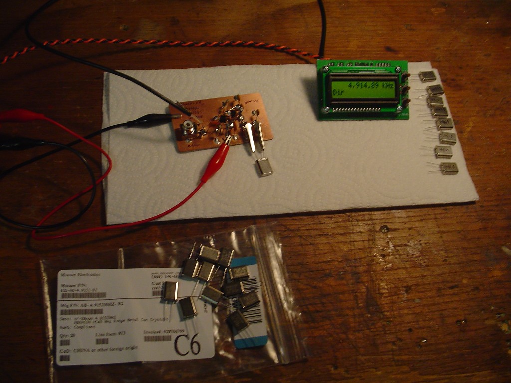
I needed to find a way to match the X1-X7 crystals ahead of
building time, or this thing would never work right. I constructed several test
oscillators to sort thru the crystals, but the darn oscillators would not oscillate.
The oscillator design that finally worked right off the bat was the crystal tester
circuit section of the “HF Test Set” by N6BM. The oscillator output would feed
the FCC-1, which I would use later in the rig anyway. I purchased 20 Abracon
4.915Mhz (+-20ppm) crystals from Mouser for 32 cents a piece and took the sweet sets for the Sierra IF..
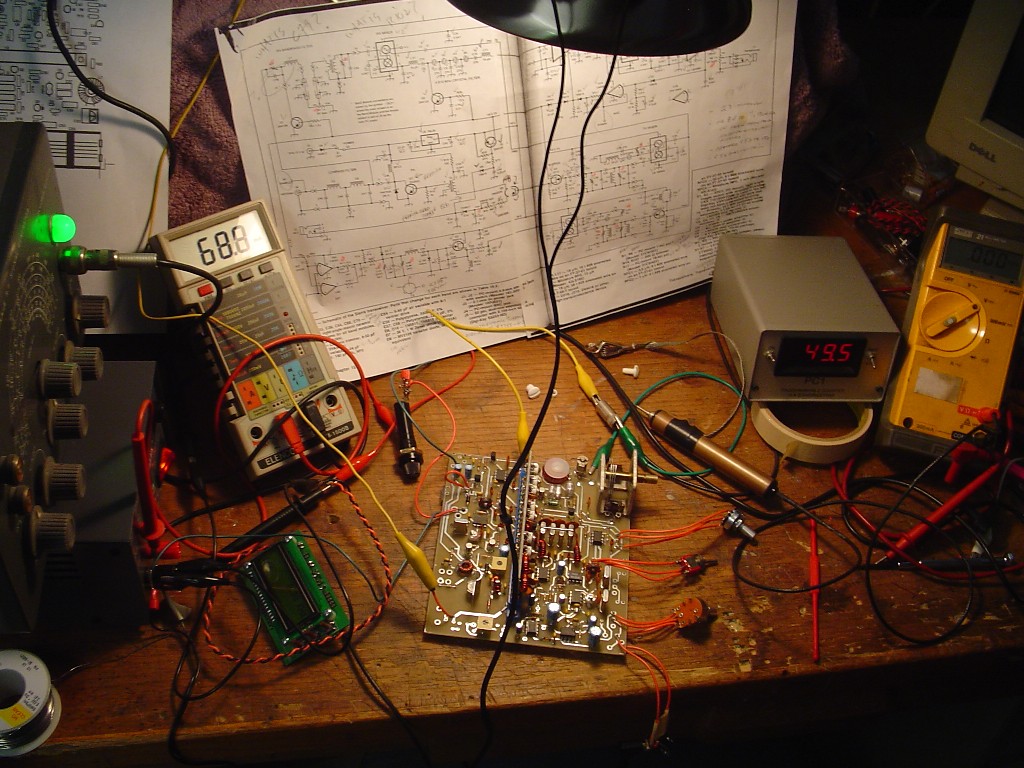
I had tried a lot of the published mods for the rig after operation was verified - but found TX output was low. None of the mods really worked for me at 12.00V. With all of the other test point signal levels acceptable, I decided to construct an additional 5w PA circuit later on. I went with the NTE278 driver and NTE341 final in the Sierra though. If there is one easy thing I would do to a Sierra, its put in the NTE341 for a little more power. It runs much cooler than the 2N3553 and although expensive – its still readily available. Note the NTE341 pinout is different than the 3N3553, requiring bending one of the leads across to the other side of the component case.
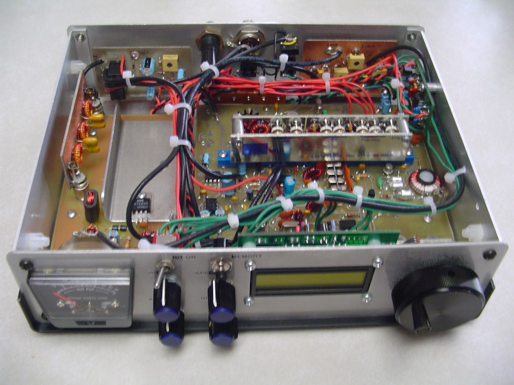
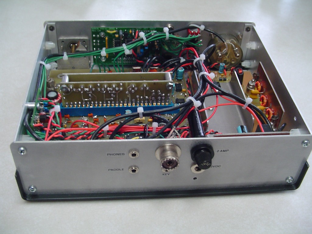
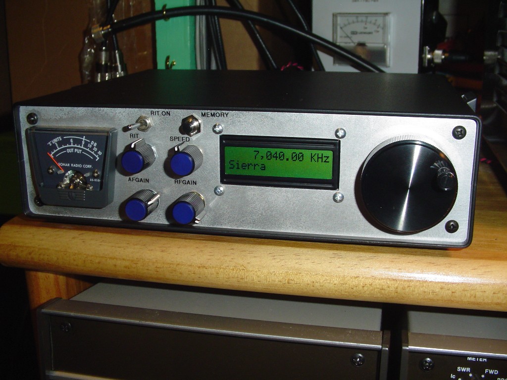
Powered up. Currently I am using the FCC-1 programmed in “User Defined” band mode and not switching the band information to the FCC-1. For reasons not presently understood by me, I have found that 40m displays about 1.5Khz low, and 30m about 700Hz low. I have not checked 20 and 17m yet for accuracy. The FCC-1 was calibrated to WWV with spectrogram on the PC and good quality headphones also. I just don’t know why I would have different accuracy on different bands with the same IF filtering. I may program the errors out in the future using the IF offset function in the FCC-1 with band switching info via a header on the band modules, but 1.5Khz max error is OK for now for use in the field.

“Norcal Keyer”
“Norcal FCC-1”
Optional metering circuitry from the ARRL article, constructed “Manhattan Style”, and driving a S/RF meter from Surplus Sales of Nebraska
“W1FB PA-5” 5w amplifier, and “Break in Delay Circuit” from his QRP books
A set of low pass, harmonic, plug in filters from the values published online at the GQRP club by G3RJV (I had trouble with the filters in the W1FB article.)
Wilderness Radio was nice enough to sell me 2 crystals by themselves for $15 each that I could not locate otherwise for a couple of the bands. Next up will probably be construction of the 80 and 15m boards.
**************************************
UPDATE:
80 and 15m band modules completed Jan '09. The 15m module is very sensitive to peaking. I picked up the 15m crystal from Wilderness radio for $15, and the 80m crystal from Mouser for .41 cents.
Unfortunately I was disappointed yet again with the FAR Circuits band module boards as these last two boards the pin contact etching spacing did not even match up with eachother let alone fit into the Sullins module connector without substantial reworking. Also the component silk was printed on different sides on these same two band module boards again!
**************************************
As I mentioned earlier, I intended to only operate the Sierra at battery powerv. With my low Sierra TX output, I decided to include an additional PA stage and not be strapped to running the rig up at 14-16v like I had read is popular for more TX output. I would trade off full-QSK for semi-QSK, but still worth it in my opinion. After construction, TX output was later tested from the Sears DieHard 12.8v portable power supply into a dummy load to reflect true operation as anticipated in the field. Here are the results:
80m 5w (Detuned for 5w output)
40m 5w
30m 3.3w
20m 2.9w
17m 1.8w
15m 1.3w
The RX was drawing 62ma with band noise only in the headphones
(The FCC-1 draws around 30ma).
I know the rig ended up being pretty big (Hence the page title) but it includes most of the items I wanted it to have at the beginning. I am very much looking forward to trying portable operation with it.
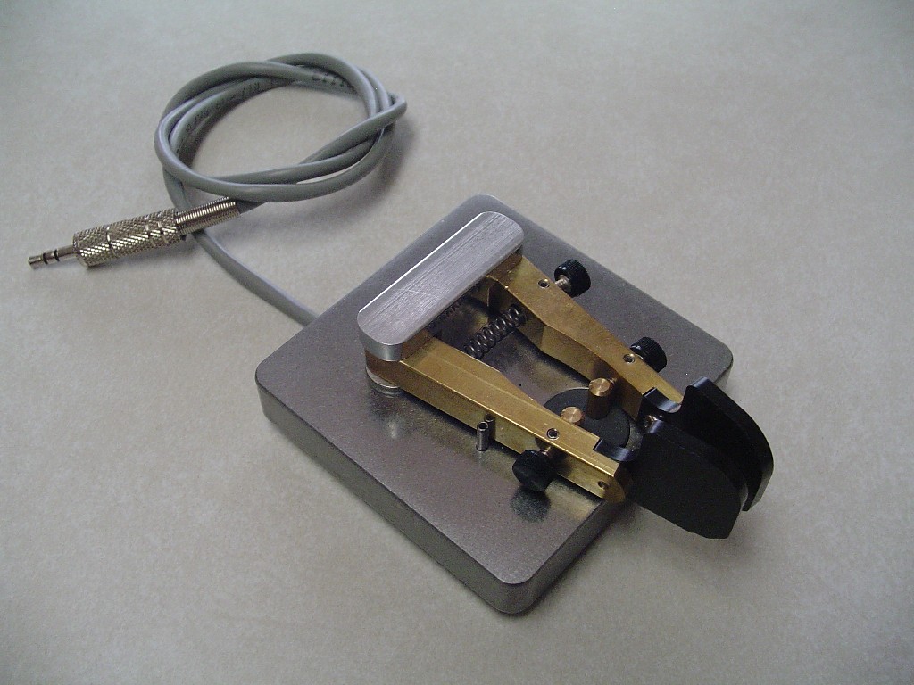
I make a habit of cleaning the contact areas of this paddle before going out to operate, as with alot of moisture in the portable environment it can cause problematic operation otherwise.
The KK-2 is built like a tank :)
Thanks for checking out this project!
